Variable chamfers - CAD tutorial
·
·
Since this is a massive part of the Monolith R1 design language, I guess it can't hurt to show how I like to do it.
The best thing about variable chamfers is that they make parts look more interesting and aesthetically pleasing. Still, they don't mess with printability and don't add significant machining time to milled part production.
- First, I create a new sketch on the face where I want the chamfer to be and I offset the contour by the chamfer sizes that I want. In this case: 0.4, 1, and 2.5mm. Then I connect these 3 lines where I want the transitions to be.
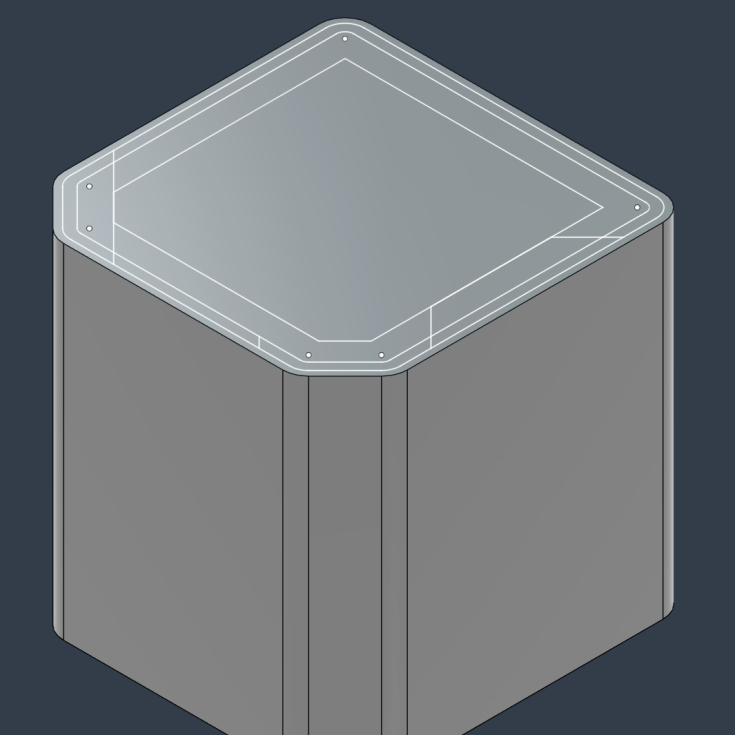
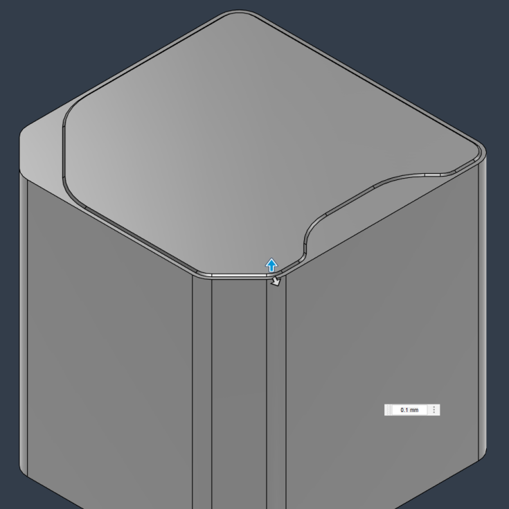
- Then I cut with the profiles of the previous sketch. The depth of the cut should be less than the smallest desired chamfer size. In this case, it's 0.1mm.
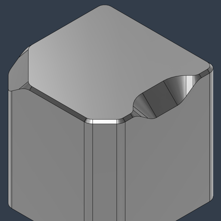
- To make the transitions more aesthetically pleasing I add fillets to every single vertical edge. In the case of milling it's important to have larger inner fillet sizes than the desired size of the chamfer there. Otherwise, the geometry would be much harder to machine on a 3-axis CNC.
- The next step is to add a 45-degree chamfer of the same size as the previous cutting depth, which is 0.1mm.
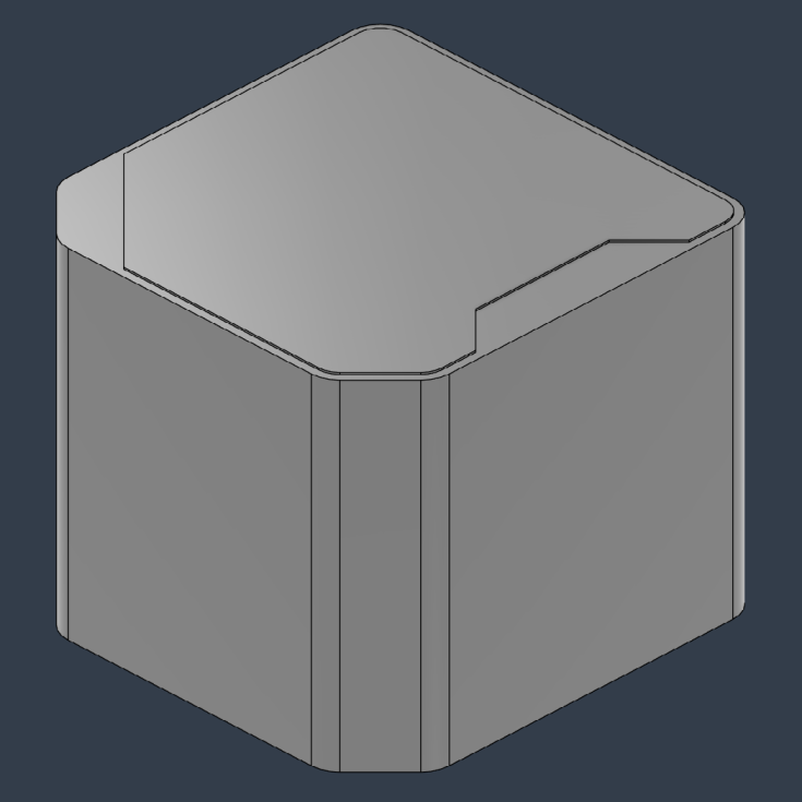
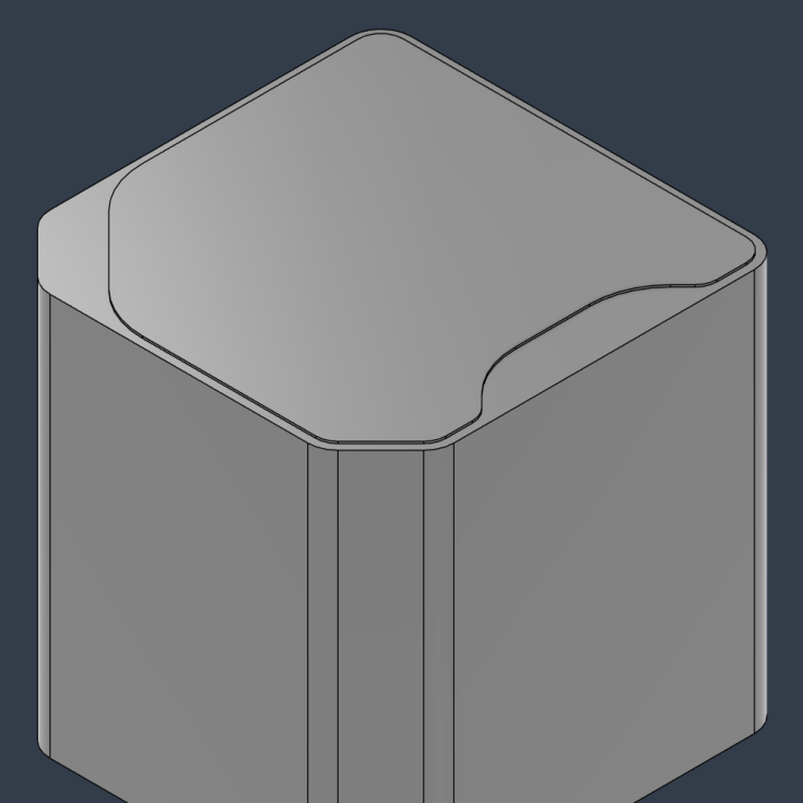
- Because the width was larger than the cutting depth, the single remaining horizontal face can be removed with a single click instead of selecting multiple faces. What's left is the variable chamfer that we wanted.
